A Patterned Coating
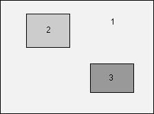
Patterned coatings have applications in such diverse areas as LCD displays, detector systems, and color filters. The manufacturing process for these coatings has much in common with the manufacture of semiconductor "chips". Although it is possible for the coatings to be completely different in the three areas, the designs for the three areas usually have one or more layers in common. The diagram below shows a side-view of the three designs.
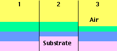
The challenge is to design the three coatings so that they have the desired reflectance, transmittance, etc. Designers can use TFCalc's multiple environments and active materials features to create these coatings.
To illustrate this method of design, we seek to create a patterned coating consisting of
four areas. The goal is to create areas that reflect three quite different colors when
illuminated by white light. This patterned coating will be manufactured as follows:
- Mask part of the glass substrate
- Deposit a number of layers -- coating A
- Remove the mask and apply another mask
- Deposit a number of layers -- coating B
- Remove the mask
In TFCalc, we use the multiple environments capability to create an environment for each of the three coatings: A+B, A, and B. The environments have two uses. They enable us to specify the performance requirements for each coating. They also let us specify how layers are transformed when we switch environments. Below is a screen shot of the Environments window.
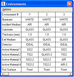
Much of the information in the Environment window is the same as in the Environment window. However, note the four active material rows. These describe how a layer's material changes in the three environments. Before creating these environments, we added new materials called SIO2-2, TIO2-2, GLASS, GLASS-2, AIR, and AIR-2 having the same indices as SIO2, TIO2, GLASS, and AIR. The first column, environment 1, represents the design for A+B. The second column, environment 2, represents the design for B; it says that the SIO2 and TIO2 layers should be replaced by GLASS and GLASS-2. The third column, environment 3, represents the design for A; it says that the SIO2-2 and TIO2-2 layers should be replaced by AIR and AIR-2.
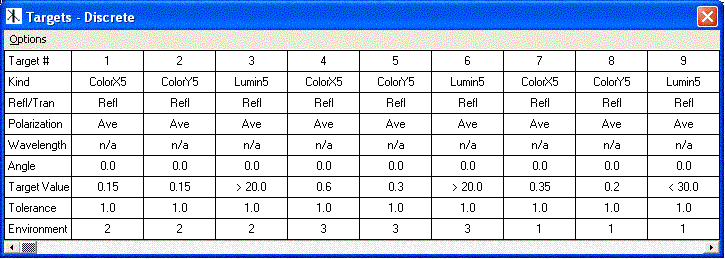
Next, we specify the performance targets for each of the A, B, and A+B coatings. The reflected color targets are as follows:
     A     x=0.6     y=0.3     Y > 20%     (reddish color)
     B     x=0.15    y=0.15    Y > 20%     (bluish color)
     A+B   x=0.35    y=0.2     Y < 30%     (purplish color)
where Y is the luminosity. We specify Y(A+B) < 30% because we desire that the luminosity of
A+B be similar to the luminosity of A and B. In general, if no requirement is placed on Y(A+B),
the luminosity would be close to Y(A) + Y(B). So by optimizing all three designs simultaneously,
we can reduce the luminosity of the A+B design. The Target window is shown below. Note that
the last row gives the environment to which the target applies.
As the starting design for the A+B coating, we use H(LH)^8 (XY)^8, where H=TIO2, L=SIO2, X=SIO2-2, and Y=TIO2-2. All of the thicknesses are 0.8 QWOT at the 550 nm reference wavelength.
Finally, we are ready to start optimizing. Because local optimization would quickly find only an inferior local minimum, we opt to use TFCalc's global search capability. We quickly scan 10000 random designs to find a set of possible designs. Then local optimization is used to refine the possible designs. We find a 26-layer design that comes close to meeting all of the performance requirements. The performance is shown below.
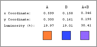
The design of A+B, starting with the layer closest to the substrate, and with thicknesses given in nm is:
    TIO2      96.06
    SIO2     309.82
    TIO2      86.00
    SIO2     101.20
    TIO2      85.36
    SIO2     116.96
    TIO2      98.20
    SIO2      35.68
    TIO2      76.30
    SIO2     154.25
    TIO2      60.90
    SIO2      80.80

    SIO2-2   104.66
    TIO2-2    51.04
    SIO2-2    65.40
    TIO2-2    31.22
    SIO2-2    78.34
    TIO2-2    51.39
    SIO2-2   223.80
    TIO2-2    38.13
    SIO2-2    53.69
    TIO2-2    29.70
    SIO2-2    64.75
    TIO2-2    48.04
    SIO2-2    71.99
    TIO2-2    14.36
The design can be improved by making some small changes and reoptimizing: (1) reduce the thickness
of layer 2 by 2 QWOTs (189 nm) and (2) remove the thin last layer.